
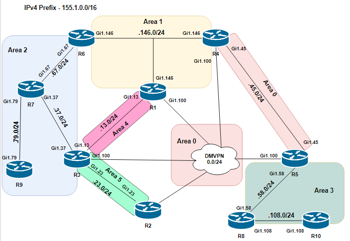
Pretty much done with EIGRP labs for now and started with OSPF instead where I found a really interesting lab regarding using non-backbone areas as transit. The traffic really didn’t behave the way I “thought” it should based on what i’ve read earlier, the lab looked like this:
Requirements
- Disable the link between R3 & R7 and make sure traffic in area 2 still can reach the rest of the network
- Modify SPF calculations so that R4 can’t be used for transit traffic in area 1 to area 0, don’t use cost
- Traffic from R9 should route via R1 to reach R8
By disabling the link between R3 - R7 traffic in area 2 will be separated from the rest of the network as traffic isn’t allowed to pass via another non-backbone area. We can verify this in R7 as it shouldn’t consider R6 an ABR.
1
2
3
4
5
6
7
8
    R7#sh ip ospf border-routers

    OSPF Router with ID (150.1.7.7) (Process ID 1)

    Base Topology (MTID 0)

    Internal Router Routing Table
    Codes: i - Intra-area route, I - Inter-area route
Checking the OSPF database we still see R3’s LSAs until they age out, but no summary-routes (LSA Type 3) are advertised from R6.
1
2
3
4
5
6
7
8
9
10
11
12
13
14
15
16
17
18
19
20
21
22
23
24
25
26
27
28
29
30
31
32
33
34
35
36
37
38
39
40
41
42
43
    R7#sh ip ospf database

    OSPF Router with ID (150.1.7.7) (Process ID 1)

    Router Link States (Area 2)

    Link ID ADV Router Age Seq# Checksum Link count
    150.1.3.3 150.1.3.3 262 0x80000002 0x002840 1
    150.1.6.6 150.1.6.6 182 0x80000003 0x0073AA 1
    150.1.7.7 150.1.7.7 181 0x80000005 0x00DD03 5
    150.1.9.9 150.1.9.9 254 0x80000002 0x008AF8 3

    Net Link States (Area 2)

    Link ID ADV Router Age Seq# Checksum
    155.1.67.6 150.1.6.6 182 0x80000001 0x00C5A1
    155.1.79.9 150.1.9.9 255 0x80000001 0x003517

    Summary Net Link States (Area 2)

    Link ID ADV Router Age Seq# Checksum
    150.1.1.1 150.1.3.3 269 0x80000001 0x00B973
    150.1.2.2 150.1.3.3 269 0x80000001 0x00A486
    150.1.3.3 150.1.3.3 319 0x80000001 0x0028D8
    150.1.4.4 150.1.3.3 269 0x80000001 0x0051C0
    150.1.5.5 150.1.3.3 279 0x80000001 0x0032DE
    150.1.6.6 150.1.3.3 253 0x80000002 0x002FDC
    150.1.8.8 150.1.3.3 248 0x80000001 0x00FC0D
    150.1.10.10 150.1.3.3 244 0x80000001 0x00DC28
    155.1.0.1 150.1.3.3 269 0x80000001 0x0079B0
    155.1.0.2 150.1.3.3 269 0x80000001 0x006FB9
    155.1.0.3 150.1.3.3 309 0x80000001 0x00FD02
    155.1.0.4 150.1.3.3 269 0x80000001 0x0032DF
    155.1.0.5 150.1.3.3 279 0x80000001 0x001EF3
    155.1.5.0 150.1.3.3 279 0x80000001 0x0023ED
    155.1.8.0 150.1.3.3 248 0x80000001 0x000C01
    155.1.10.0 150.1.3.3 244 0x80000001 0x00FF0A
    155.1.13.0 150.1.3.3 319 0x80000001 0x00965E
    155.1.23.0 150.1.3.3 319 0x80000001 0x0028C2
    155.1.45.0 150.1.3.3 279 0x80000001 0x00697F
    155.1.58.0 150.1.3.3 279 0x80000001 0x00D902
    155.1.108.0 150.1.3.3 248 0x80000001 0x00BBEC
    155.1.146.0 150.1.3.3 269 0x80000001 0x00186A
We solve this by setting up a virtual link between R6 & R1, remember we’re not supposed to send area 2’s traffic to R4.
1
2
3
4
5
6
7
8
9
10
11
12
13
14
15
16
17
18
19
20
21
22
23
24
25
26
27
28
29
30
31
32
33
34
35
36
37
38
39
40
41
42
43
44
45
46
47
48
49
50
51
52
53
54
55
56
57
58
59
60
61
62
63
64
65
66
67
    ! R6

    router ospf 1
     area 1 virtual-link 150.1.1.1

    ! R1

    router ospf 1
     area 1 virtual-link 150.1.6.6

    R6 will now have a virtual connection to area 0 and can now act as an ABR to area 2.

    R6#sh ip ospf neighbor

    Neighbor ID Pri State Dead Time Address Interface
    150.1.1.1 0 FULL/ - - 155.1.146.1 OSPF_VL0
    150.1.1.1 1 FULL/DROTHER 00:00:35 155.1.146.1 GigabitEthernet1.146
    150.1.4.4 1 FULL/BDR 00:00:37 155.1.146.4 GigabitEthernet1.146
    150.1.7.7 1 FULL/BDR 00:00:31 155.1.67.7 GigabitEthernet1.67

    R6#sh ip ospf interface
    OSPF_VL0 is up, line protocol is up
    Internet Address 155.1.146.6/24, Area 0, Attached via Not Attached
    Process ID 1, Router ID 150.1.6.6, Network Type VIRTUAL_LINK, Cost: 1
    Topology-MTID Cost Disabled Shutdown Topology Name
    0 1 no no Base
    Configured as demand circuit
    Run as demand circuit
    DoNotAge LSA allowed
    Transmit Delay is 1 sec, State POINT_TO_POINT
    Timer intervals configured, Hello 10, Dead 40, Wait 40, Retransmit 5
    oob-resync timeout 40
    Hello due in 00:00:08
    Supports Link-local Signaling (LLS)
    Cisco NSF helper support enabled
    IETF NSF helper support enabled
    Can not be protected by per-prefix Loop-Free FastReroute
    Can not be used for per-prefix Loop-Free FastReroute repair paths
    Index 1/1/4, flood queue length 0
    Next 0x0(0)/0x0(0)/0x0(0)
    Last flood scan length is 1, maximum is 1
    Last flood scan time is 0 msec, maximum is 0 msec
    Neighbor Count is 1, Adjacent neighbor count is 1
    **Adjacent with neighbor 150.1.1.1 (Hello suppressed)**
    Suppress hello for 1 neighbor(s)

    R6#sh ip ospf database self-originate

    OSPF Router with ID (150.1.6.6) (Process ID 1)

    Router Link States (Area 0)

    Link ID ADV Router Age Seq# Checksum Link count
    150.1.6.6 150.1.6.6 739 0x80000003 0x00F126 1

    Summary Net Link States (Area 0)

    Link ID ADV Router Age Seq# Checksum
    150.1.6.6 150.1.6.6 739 0x80000002 0x00BF34
    150.1.7.7 150.1.6.6 739 0x80000002 0x00B43C
    150.1.9.9 150.1.6.6 739 0x80000002 0x009457
    155.1.7.0 150.1.6.6 739 0x80000002 0x00B939
    155.1.9.0 150.1.6.6 739 0x80000002 0x00AD42
    155.1.37.0 150.1.6.6 739 0x80000002 0x006E66
    155.1.67.0 150.1.6.6 739 0x80000002 0x00199E
    155.1.79.0 150.1.6.6 739 0x80000002 0x009E0C
    155.1.146.0 150.1.6.6 739 0x80000002 0x00B0B7
R7 now see’s R6 as an ABR which in turn will send summary-LSAs for the rest of the network.
1
2
3
4
5
6
7
8
9
10
11
12
13
14
15
16
17
18
19
20
21
22
23
24
25
26
27
28
29
30
31
32
33
    R7#sh ip ospf border-routers

    OSPF Router with ID (150.1.7.7) (Process ID 1)

    Base Topology (MTID 0)

    Internal Router Routing Table
    Codes: i - Intra-area route, I - Inter-area route

    i 150.1.6.6 [1] via 155.1.67.6, GigabitEthernet1.67, ABR, Area 2, SPF 6

    R7#sh ip ospf database | beg Summary
    Summary Net Link States (Area 2)

    Link ID ADV Router Age Seq# Checksum
    150.1.1.1 150.1.3.3 814 0x80000001 0x00B973
    **150.1.1.1 150.1.6.6 311 0x80000001 0x0035C8**
    150.1.2.2 150.1.3.3 814 0x80000001 0x00A486
    **150.1.2.2 150.1.6.6 306 0x80000002 0x005CB1**
    150.1.3.3 150.1.3.3 864 0x80000001 0x0028D8
    **150.1.3.3 150.1.6.6 306 0x80000002 0x0047C4**
    150.1.4.4 150.1.3.3 814 0x80000001 0x0051C0
    **150.1.4.4 150.1.6.6 306 0x80000002 0x00F303**
    150.1.5.5 150.1.3.3 824 0x80000001 0x0032D
    ....

    R7#sh ip route 150.1.8.8
    Routing entry for 150.1.8.8/32
    Known via "ospf 1", distance 110, metric 5, type inter area
    Last update from 155.1.67.6 on GigabitEthernet1.67, 00:06:17 ago
    Routing Descriptor Blocks:
    *** 155.1.67.6, from 150.1.6.6, 00:06:17 ago, via GigabitEthernet1.67**
    Route metric is 5, traffic share count is 1
Even if we enable R3’s link to R7 now the traffic will still prefer the route via R6 as it has a lower metric to R8, indifferent to the fact that a virtual-link is needed to traverse that area.
1
2
3
4
5
6
7
8
9
10
11
12
13
14
15
16
17
18
19
20
21
22
23
24
25
26
27
    R7#sh ip ospf database summary 150.1.8.8

    OSPF Router with ID (150.1.7.7) (Process ID 1)

    Summary Net Link States (Area 2)

    LS age: 976
    Options: (No TOS-capability, DC, Upward)
    LS Type: Summary Links(Network)
    **Link State ID: 150.1.8.8 (summary Network Number)**
    **Advertising Router: 150.1.3.3**
    LS Seq Number: 80000001
    Checksum: 0xFC0D
    Length: 28
    Network Mask: /32
    **MTID: 0 Metric: 1002**

    LS age: 493
    Options: (No TOS-capability, DC, Upward)
    LS Type: Summary Links(Network)
    **Link State ID: 150.1.8.8 (summary Network Number)**
    **Advertising Router: 150.1.6.6**
    LS Seq Number: 80000001
    Checksum: 0xB538
    Length: 28
    Network Mask: /32
    **MTID: 0 Metric: 4**
By checking the metric you may already have realized how the traffic is currently flowing to R8 which was a surprise to myself. By setting up a virtual-link between R6 & R1 I thought that the transit traffic from area 2 would also route that way. But no, not at all!
1
2
3
4
5
6
7
8
    R7#traceroute 150.1.8.8 numeric
    Type escape sequence to abort.
    Tracing the route to 150.1.8.8
    VRF info: (vrf in name/id, vrf out name/id)
    1 155.1.67.6 7 msec 3 msec 4 msec
    2 155.1.146.4 5 msec 5 msec 5 msec
    3 155.1.45.5 6 msec 6 msec 6 msec
    4 155.1.58.8 6 msec * 6 msec
How come? Let’s dive in to R6’s database.
1
2
3
4
5
6
7
8
9
10
11
12
13
14
15
16
    R6#sh ip ospf database summary 150.1.8.8

    OSPF Router with ID (150.1.6.6) (Process ID 1)

    Summary Net Link States (Area 0)

    LS age: 484 (DoNotAge)
    Options: (No TOS-capability, DC, Upward)
    LS Type: Summary Links(Network)
    Link State ID: 150.1.8.8 (summary Network Number)
    **Advertising Router: 150.1.5.5**
    LS Seq Number: 80000001
    Checksum: 0xAE43
    Length: 28
    Network Mask: /32
    MTID: 0 **Metric: 2**
So R5 is the ABR originating the summary-LSA with a metric of 2, so what is R6’s preferred path to R5?
1
2
3
4
5
6
7
8
9
10
11
12
13
14
15
16
17
18
19
20
21
22
23
24
25
26
27
28
29
30
31
32
33
34
    R6# sh ip ospf database router 150.1.5.5

    OSPF Router with ID (150.1.6.6) (Process ID 1)

    Router Link States (Area 0)

    LS age: 501 (DoNotAge)
    Options: (No TOS-capability, DC)
    LS Type: Router Links
    Link State ID: 150.1.5.5
    Advertising Router: 150.1.5.5
    LS Seq Number: 80000004
    Checksum: 0x56B2
    Length: 108
    Area Border Router
    Number of Links: 7

    Link connected to: a Stub Network
    (Link ID) Network/subnet number: 150.1.5.5
    (Link Data) Network Mask: 255.255.255.255
    Number of MTID metrics: 0
    TOS 0 Metrics: 1

    **Link connected to: a Transit Network**
    **(Link ID) Designated Router address: 155.1.45.5**
    **(Link Data) Router Interface address: 155.1.45.5**
    Number of MTID metrics: 0
    TOS 0 **Metrics: 1**

    **Link connected to: another Router (point-to-point)**
    **(Link ID) Neighboring Router ID: 150.1.4.4**
    **(Link Data) Router Interface address: 155.1.0.5**
    Number of MTID metrics: 0
    TOS 0 **Metrics: 1000**
Traffic is going directly from R6 to R4 even though that it isn’t R6s virtual-link to area 0! This functionality is further explained in RFC 2328 section 16.3, examining transit area’s summary-LSAs.
16.3. Examining transit areas’ summary-LSAs
This step is only performed by area border routers attached to one or more non-backbone areas that are capable of carrying transit traffic (i.e., "transit areas", or those areas whose TransitCapability parameter has been set to TRUE in Step 2 of the Dijkstra algorithm (see Section 16.1). The purpose of the calculation below is to examine the transit areas to see whether they provide any better (shorter) paths than the paths previously calculated in Sections 16.1 and 16.2. Any paths found that are better than or equal to previously discovered paths are installed in the routing table.
Apparently the parameter TransitCapability is on by default in all cisco-routers, which results in R6 preferring the route via R4 as it has lower metric even though the route is passing a non-backbone area. This functionality can be disabled however and that is also how we solve the labs requirement that traffic has to pass via R1.
1
2
3
4
    ! R6

    router ospf 1
    no capability transit
R6’s metric to R8 is updated to reflect the new path via R1:
1
2
3
4
5
6
7
8
9
10
11
12
13
14
15
16
    R6#sh ip route 150.1.8.8
    Routing entry for 150.1.8.8/32
    Known via "ospf 1", distance 110, metric 1003, type inter area
    Last update from 155.1.146.1 on GigabitEthernet1.146, 00:00:25 ago
    Routing Descriptor Blocks:
    * 155.1.146.1, from 150.1.5.5, 00:00:25 ago, via GigabitEthernet1.146
    Route metric is 1003, traffic share count is 1

    R6#traceroute 150.1.8.8
    Type escape sequence to abort.
    Tracing the route to 150.1.8.8
    VRF info: (vrf in name/id, vrf out name/id)
    1 155.1.146.1 5 msec 4 msec 4 msec
    2 155.1.146.4 5 msec 5 msec 5 msec
    3 155.1.45.5 7 msec 6 msec 7 msec
    4 155.1.58.8 7 msec * 7 msec
Very interesting! Even though it’s uses may be very specific and not commonly used in the “real world” it feels like it certainly can be something that they throw at you at the CCIE-exam.